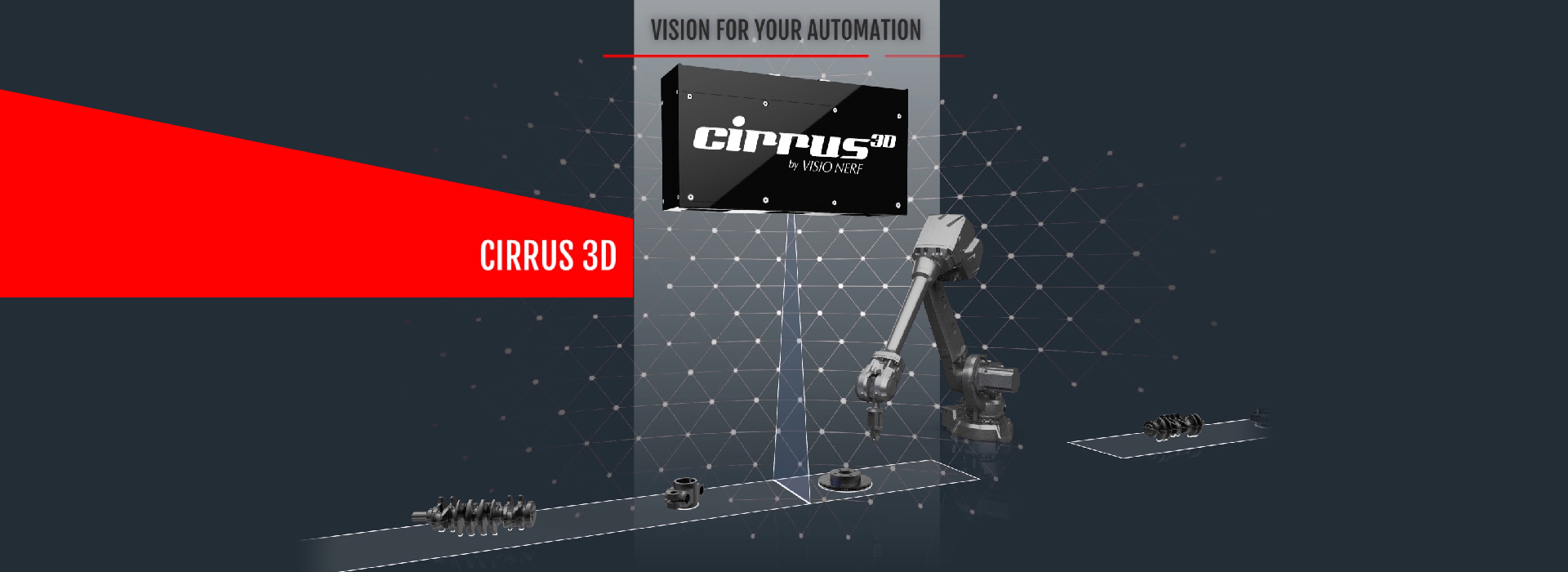
3D Guidance : Robotic Guidance solution
BASIC PRINCIPLE
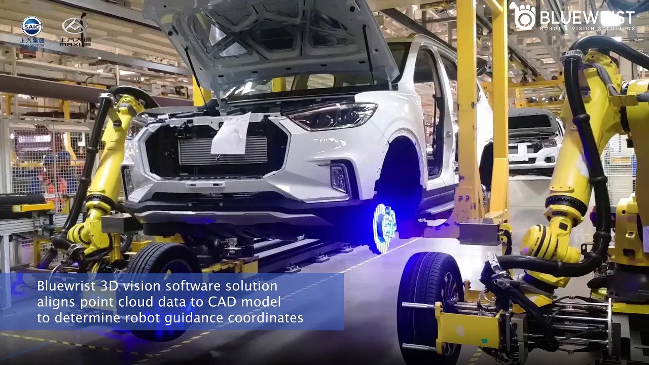
Solution for the automation of precision operations on products with unknown shape or positioning. Solution for automating assembly operations on production lines. The analysis of the virtual work scene makes it possible to optimize the processes for the assembly operations or for the precision operations like machining, deburring, etc. The association of the point cloud with the CAD model data of the part makes it possible to better compensate for its positioning and shape defects
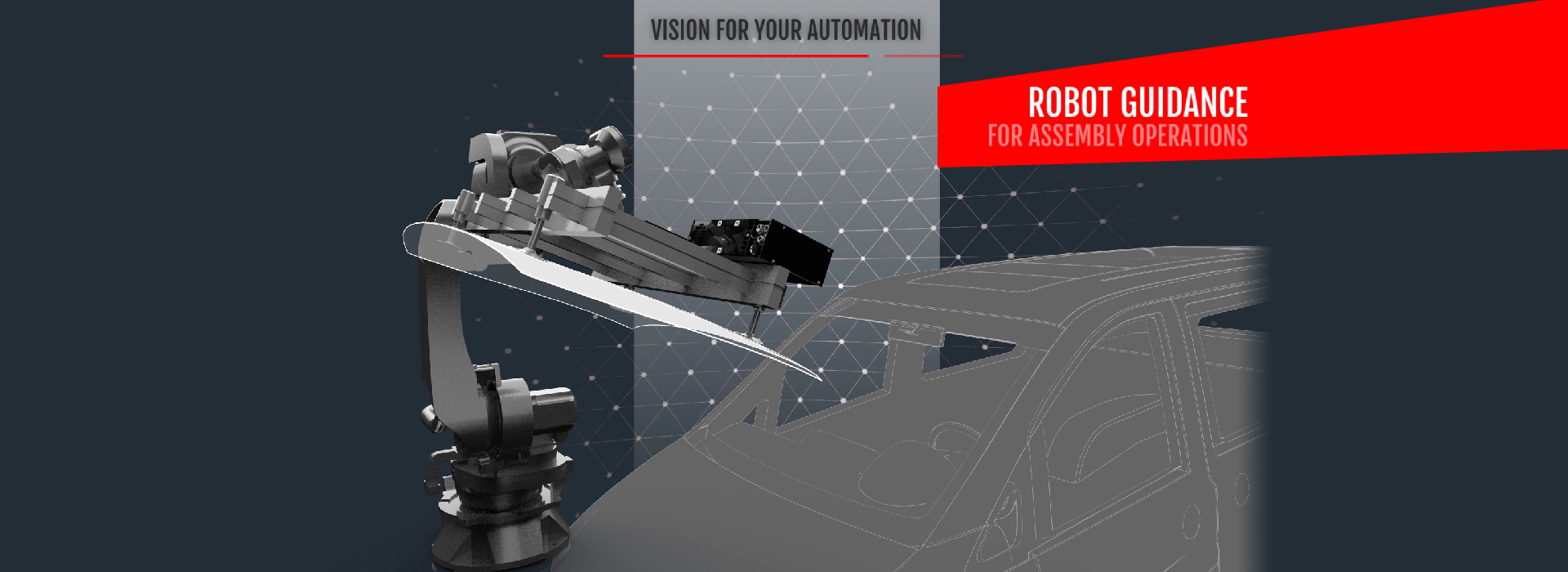
The need to build a robotic environment is a key feature in production. However, it is sometimes quite hard to guide the robot arm precisely from one point to another. Thus, the 3D vision is a very powerful tool to cope with these issues and to abide to the reduction of the cycle time, increase in productivity and repeatability of the work. The use of a robotic arm also prevents the operators from muscular disorders and low-added value painful tasks.
INDUSTRIAL NEEDS:
- Automating work precision despite variations in the shape of parts?
- Strong shape variation of parts with low manufacturing tolerances?
- Parts with high production costs in small quantities?
- Parts with critical operating reliability?
- With 3D control that can be used on misshaped parts, VISIO NERF makes the incompatible compatible!
- Precise work on variable shapes!


HOW IT WORKS
The 3D machine vision can be embedded on the robot or fixed above the volume of work. The 3D vision should then be calibrated on the robot coordinate frame for the two systems to collaborate together.
If we set, as an example, the cutting of casting jets and sawing operations on cylinder heads. A standard application in which 3D vision technology is used is the location of cylinder heads and the identification of the cylinder head reference by the 3D sensor. In the first step of the process, the cylinder heads arrive on a conveyor at the exit of the casting process, they are arranged randomly with the same side always facing up. The parts are raw (or as-cast) with sand residues as well as feeders and casting jets still present. The cylinder heads are scanned by the 3D sensor, they are precisely located in space and identified. With the help of a CAD model library, the software determines the reference of the detected cylinder head by comparing the point cloud with the CAD model, without taking into account the residues on the part.
Once the part recognition and location of the part is done, the 3D sensor sends the coordinates to the robot so that it can pick up the part with its gripper. The robot then positions the yoke under the 3D sensor in a determined orientation, always presenting the same face of the yoke to the sensor to locate it precisely in the jaws of its gripper and to allow it to correct its grip hampered or altered by the residues. All that remains for the robot to do is to bring the cylinder head in front of the cutting tools of the casting jets and to move it along a sawing trajectory perfectly adjusted to its grip. The 3D vision system allows precise localization of the part for an optimal cutting of the cylinder head and a reduced cycle time.
Finally, the robot must also test that it is able to reach all the positions of the trajectory to be followed, and that it is not in positions of singularity for it. The three guidance stages are measurement, registration and machining. In the measurement step, the robot moves the part in front of the fixed sensor or moves the on-board sensor in front of the part to measure the different areas. During the registration, the robot assumes that the part is locally compliant with the CAD model and asks the processing software to calculate, for each of the different zones to be machined, a local reference of the part. Finally, during machining, the robot machines each zone by applying to the trajectory of its machining tool, the correction based on the local coordinate system determined for this zone.
3D VISION ADVANTAGES
The 3D vision solution has many advantages. First of all, it brings an adaptability to the constraints of production lines with a fast-processing time. Then, it is economic because it avoids a mechanical setting in position for each model of part. The 3D vision also offers a speed of implementation and change of part thanks to the use of the CAD model of the part. It is also independent of the machine tool. Finally, it allows the optimization of the trajectories by local recalibrations to take into account the shape defects of the part, which proves to be particularly useful for foundry parts.
INDUSTRIAL NEEDS:
- Automating work precision despite variations in the shape of parts?
- Strong shape variation of parts with low manufacturing tolerances?
- Parts with high production costs in small quantities?
- Parts with critical operating reliability?
- With 3D control that can be used on misshaped parts, VISIO NERF makes the incompatible compatible!
- Precise work on variable shapes!
Automate Precision Work
Robot Guidance: For cost-effective automation of the finishing or machining of mechanical parts
For cost-effective automation of assembly lines.
01
Numbering
The robot moves the part in front of the fixed sensor or moves the sensor in front of the part to measure the different zones.

02
Guidance
The robot makes the assumption that the part is locally compliant with the CAD model and requests the processing software to calculate local coordinates of the part, for each of the different areas to be worked with precision or assembly operation

03
Precision work operation step
The robot mills each area by applying the correction to the trajectory of its machining tool based on the local coordinates determined for this area